Monday, February 20, 2017

Making the Mast

Making the Mast, Spars, Rudder and Daggerboard


Before I could shave the mast I needed to make a bodger's horse. It has been a long time since I made one of these things. Very handy.


I headed out into the woods to look for a recently dead tree the right size and straight as an arrow. I did not want to take out a live tree if I could have avoided it. No luck. I found one the right size but it was decidedly not straight. I thought I could straighten in out when I carved it but it turns out there is very little room for this. Lesson: find a straight tree. So the mast will have a few minor curves in it. No worries --  it will definitely look hand carved.


Monday, February 6, 2017

Acorn Images

Building Iain Oughtred's Acorn Tender


The Overview
Sadly I cannot find any images of the beginning of the build. The initial construction of the setup and molds was easy enough. I really enjoyed lining out the strakes with small battons as that was the first time I could visualize the final hull appearance. After placing the keelson even the dreaded garboard strakes went on without issue. However, from that point on creating a template for each pair of strakes was a challenge. I tried spiling, and using a thin sheet of luan bent over the battons in an attempt to figure out the exact shape of the next strake. The simple luan technique worked well until I got to the strakes that were longer than the plywood and I certainly wasn't going to scarf every template. Eventually what worked the best was laying a stiff plastic sheet, about 6mil, over the hull and tracing the edges of the lining battons. A couple of stakes were a smidgen off, but not bad and happily are not very noticeable in the final product.

Outer stem attached, keel blanks positioned.

This part of the build is where things were fun and fast. Finally I could see the end of the hull. I laminated the outer stem at the same time I laminated the inner stem so it was ready to go. Having that piece hanging around for 6 months was demoralizing. Attaching the gunwales and keel was simple and seamless.

Attaching the outer keel, clamping from the cieling.

Using a spanish windlass to bend the aft end of the outer keel.
Outer keel in place, shaping begins, starting outer gunwales.

Attaching inner gunwales, seat risers in place.
Placing the seat risers stalled me for awhile, trying to figure out something resembling level when the boat is sitting the water. Eventually I decided it really didn't matter as long as it was symmetrical and at the appropriate height where the daggerboard case was to be installed -- this would act as a center support for the seat.

Second strip of the starboard inner gunwale is glued.
Gunwales complete, breasthook attached, daggerboard case gluing up and seats fitted.
Prepping the hull for paint

Setting up the hardware


Hull, sole and under the sole painted, seats dry fitted.

First coats of varnish.


Closeup of stem and breasthook.
Figuring out how to make the sole supports level was another tricky moment. As always, after fussing with it until I got too frustrated I simply chose to go for it, time was running out. It came out fine.

All wooden parts attached, multiple coats of varnish.
Hardware added, sole in place, all done ... for now.


The finish work was rushed and incomplete as we were heading to the northern neck of Virginia in a week. I will eventually get back to it and add another 6 coats of varnish.

Towing behind Elizabeth.

Rowing to Kilmarnock.

The first successful trip, resting at Kilmarnock.

Next Up: the mast, daggerboard and rudder. I already made the sail.

Monday, October 26, 2015

Start the Engine and Look for Leaks

Final test:


With all the parts back in their respective locations, all fluids filled and a temporary wooden plug shoved into the oil fill hole, I was ready to start the engine and see what I screwed up. I was seriously expecting some obnoxious clanking sound indicating some bit or another was left lying about inside the case. I was wrong. The engine started normally, sounded as it always had and best of all the oil pressure was back! I was now getting about 70 psi at half to three-quarters throttle and about 45 at idle. Problem solved. I only wish I knew what I did.

All done. Looks no different.
Okay, I think I really do know and it is rather embarrassing to admit that I probably did not need to replace the oil pump or any of the rubber or gaskets inside the case. When I had the case off I pulled a couple of bolts off because it was not obvious what they did or what lay behind them. One of the bolts looked suspiciously like the bolts that sealed the two pressure release valves on the oil filter assembly. These pressure relief valves are very simple -- just a spring with a ball bearing in a channel. The spring holds the ball against a seal and when the pressure is too high the spring compresses, the ball moves and the oil pressure is released back into the crankcase. Looking at the exploded parts diagram it appeared that this was another of those relief valves but did not have the spring or ball inside. This valve was not mentioned in the service manual so I only knew of it from the parts diagram. I wasn't sure if this was one of the modifications to the engine that Universal had made or whether the spring and ball should really be there and just were missing. I ordered the parts anyway and this, their absence, was, I suspect, the reason for the low oil pressure. Of course, that means that I had been running the engine for four years with low oil pressure. I have no idea why those bits were missing. Sigh. So now I have a new oil pump, new rubber and gaskets inside the timing case and oil pressure. Hopefully I will not have to repeat this for another decade or two.

Monday, October 19, 2015

Reassembly

Reassembly

Putting it all back together is just the opposite of taking it apart. Hopefully you kept track of all the bolts and other bits. The first step is to clean the two faces where the gasket will be -- on the case and on the block. I used a plastic scrub pad and 400 grit sandpaper for this job. The case gasket is large and complicated and you might want to use a spray adhesive to attach it just to make sure it doesn't move on you. In my case it worked fine without.

Next is reassembling the bits in the case and on the block. The exploded parts diagram referenced in the previous "parts" post is very useful here. These include:

  • The three small o-rings on the case that seal the channels around the oil filter. These I replaced.
  • Replace the large o-ring around the coolant pipe that sticks out on the top of the block.
  • Reassemble the crankshaft -- large washer, o-ring, and collar.
  • Make sure the part that connects the raw water pump is aligned with the slot in the timing gear.
Now all that remains is to line up the case and as you put it in place gently slip the crankshaft oil seal over the crankshaft. Push the case toward the block as far as it will go. In my case, the raw water pump attachment was not perfectly aligned with the timing gear so I put a pair of vice grips on the splined end of the crankshaft and slowly turned the shaft while pressing on the case until the case was flush with the block and gasket. Before starting all this I laid out the four corner case bolts and had a small cup of oil ready. The case bolts should go in "wet", that is dipped in oil, to prevent leakage from the back of the bolts. I inserted the four corner bolts to hold the case it place, then put in the rest of the bolts. Again I do not know what the torque specs on these bolts are so I tightened them as much as I dared. The case is now bolted in place.

Then we reassemble the rest of the bits:
  • The hoses to the raw water pump. 
  • The short hose that connects the internal coolant pump to the block.
  • The coolant hose on the lower right side of the case.
  • The gasket for the speed control assembly.
  • The two springs inside the speed control assembly. These were easy to attach with the case in place. The small spring attaches to the right hand lever that is coming out of the block and to a stud on the inside of the case. The large spring attaches to the left hand lever and to the triangular lever on the speed control plate.
  • Bolt down the spring control plate.
  • Attach the throttle linkage to the spring control plate.
  • Replace the windsor key in the crankshaft if you have not done that yet.
  • Attach the crankshaft pulley, large washer and nut. Tighten the nut which will push the pulley on to the shaft.
  • Put the alternator back and reattach the wires
  • Place and tighten the alternator belt.
  • Attach the air breather assembly.
The last step is to refill all the fluids -- oil and coolant. Oh, and don't knock the oil filler plug into the only utterly inaccessible spot in the engine compartment. This will provoke cursing and self-loathing. Trust me. When adding coolant remove the plug from the thermostat housing and fill that area with coolant as well as the main reservoir. Learned that the hard way too.


Sunday, October 18, 2015

Removing the front gear case

The Gear Case

Removing the gear case is as simple as removing the 11 bolts around the edges. Each bolt is a different length so I made a map and labeled them as I took them out. It will make putting the right bolt back in the right place easy.

The case came off without a hitch, though some of the bolts were very tight and corroded. Thankfully none broke in the process. It would probably have been a good idea to hit those bolts that can be located on the block with PB Blaster or some other penetrating oil. I lucked out.

There is a windsor key on the crankshaft that keys the balancing pulley. I should have removed this before removing the case as the crankshaft oil seal had to pass over it. Thankfully I did not damage the seal, but I might have. Better safe than sorry. Next time.

Once the case was off, the timing gears and the oil pump were exposed. In the picture to the right the upper right hand gear is the camshaft gear. The upper left is the timing gear connected to the timing pump. The middle gear connects the crankshaft gear below to both the camshaft and the timing gear. The oil pump gear is the small gear below the crankshaft.

In order to remove the oil pump gear one must first remove the windsor key, collar and oil deflecting washer that are on the crankshaft. The windsor key is the only potentially difficult part. I tried prying it off, banging on it, vice grips, heat -- to no avail. Joe, one of my boat neighbors and retired metalworker was nearby and said that an "old timer" told him to just tap it gently a couple of hundred times with a ball peen hammer and it will eventually loosen. Then it can be removed with pliers. Joe offered to give it a try and had the key out in about five minutes. Yes, I felt rather stupid but was pleased to learn this trick. I have a plastic headed hammer that I use to bang on metal, especially aluminum, so I don't damage it. If you are using a ball peen be careful not to damage the key too much or you will wind up replacing it. Once the key is removed the collar, o-ring and large washer come off easily. Now you are ready to pull the oil pump gear.

There is a nut on the oil pump shaft and a soft, bent lock washer that must be removed before the gear will come off. A small gear puller makes removing the gear easy. It is just on a tapered shaft. As with the crankshaft pulley start gently until you feel the gear start to come off. Once this gear is removed the oil pump will unbolt with four bolts in the the corners. The original pump had 3 bolts that attached the two parts of the pump housing together. The replacement pump had only one. In any case, there is a small, shallow cylindrical extrusion on the back center of the pump that positions the pump in the block. This is a very tight fit and required a bit of tapping around the edges to spin the pump loose from the gasket. Once the pump is removed all that is left is to scrape off the gasket and clean the block, add the new gasket, making sure the holes all line up and bolt on the new pump. I have no idea what the torque specs are on these bolts so I tightened them as much as I dared. Aluminium threads strip easy.

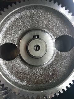
You may recall that I thought the cause of my low oil pressure was the camshaft plug coming out of the end of the shaft. As you can see on the image to the left, the plug is still in place. This was worrying. Additionally I could see no visible wear on the old oil pump so perhaps all this was in vein.

There is a plug on the other end of the camshaft and I spent some time asking around to see if anyone had removed their camshaft and how it was attached at the other end. It looked like a big job, with the header and rocker arms having to come off so all the valves could be raised to create enough clearance for the shaft to come out.

Having just spent about 4K on the boat over the summer I really did not want to undertake the expense of paying a mechanic to remove the shaft. If I had the engine out and sitting on the bench it would have been a piece of cake and I would not have hesitated to give it a try. So I dithered and dwelled on the problem for a couple of weeks. In the end I decided that I had spent enough money on the boat this year and would just reassemble the case and deal with it in the spring. This was frustrating. Oddly, I would have been happier if the damn camshaft plug was missing!